Index / Work / N° 11
Project N°11 of 24
CategoryControl
Year2025

State-Space Analysis & Control Systems Engineering

Analyzed a provided multi-mass dynamic system (Simscape Multibody) and engineered classical and modern control architectures within MATLAB to achieve strict performance requirements.

Key Engineering Contributions

  1. 01
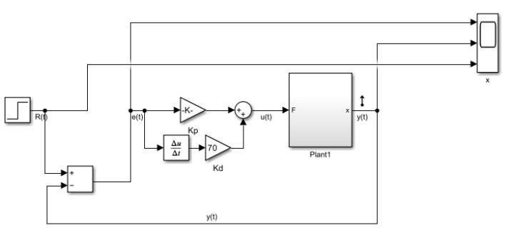
    Mathematical Modeling & Verification: Derived the state-space representation of a coupled double spring-mass-damper system. Verified the mathematical model's accuracy by running comparative step-response simulations against the physical Simscape plant.
  2. 02
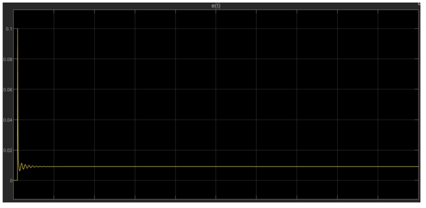
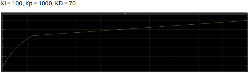
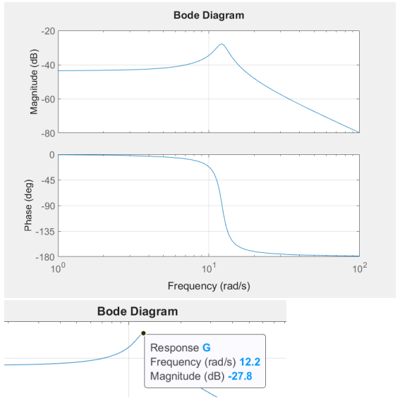
    PID Control & Frequency Analysis: Analytically designed and iteratively tuned a PID controller to minimize steady-state error while managing the trade-offs between tracking accuracy and system damping. Evaluated the control system's tracking limits across varying input frequencies using Bode plots, successfully identifying the 12.2 rad/s cutoff frequency.
  3. 03
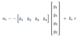
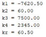
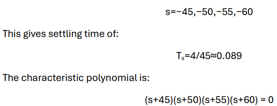
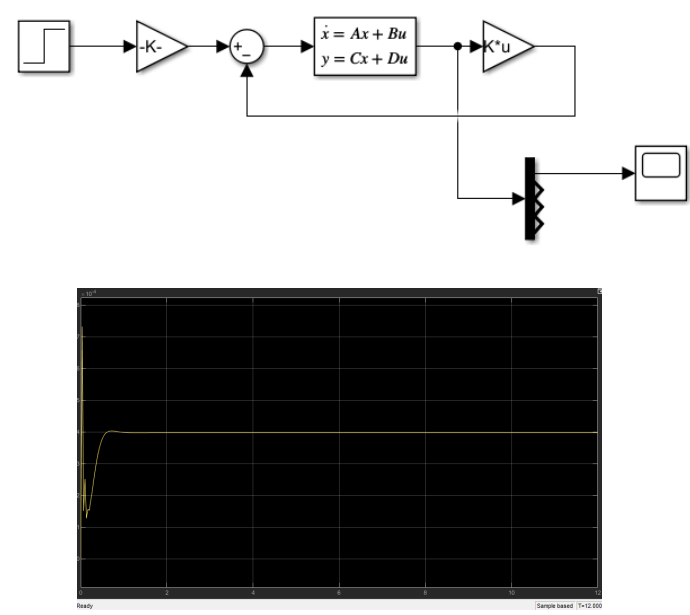
    State-Feedback Control Implementation: Engineered a modern state-feedback controller using analytical pole placement (s = -45, -50, -55, -60) to enforce strict performance constraints. Calculated optimal gain matrices to achieve a rapid settling time of less than 0.1 seconds while ensuring critical damping.

Visual Documentation

Simulink model of the PD controller
Figure 1
01.png
Simulink model of the PD controller
Chart of error propagation over time when reference step is r(t) = 0.1. The Kp v
Figure 2
02.png
Chart of error propagation over time when reference step is r(t) = 0.1. The Kp value is about 1000 while the Kd value is about 70 which produces a 10% error as requested by the system desired paramete
Chart of error propagation over time when reference step is r(t) = 0.1. The Kp value is about 1000 while the Kd value is about 70 which produces a 10% error as requested by the system desired parameters.
To minimize steady state error, a Ki value of 100 was chosen. The error propagat
Figure 3
03.png
To minimize steady state error, a Ki value of 100 was chosen. The error propagation may be seen above over time.
Bode Diagram of the Closed Transfer Function which shows the cut off frequency o
Figure 4
04.png
Bode Diagram of the Closed Transfer Function which shows the cut off frequency of 12.2 rad/s (1.94 Hz).
The selected poles and the calculated k values for the state-feedback controller (image 1 of 3)
Figure 5.1
05-1.png
Part 1 of 3
The selected poles and the calculated k values for the state-feedback controller (image 2 of 3)
Figure 5.2
05-2.png
Part 2 of 3
The selected poles and the calculated k values for the state-feedback controller (image 3 of 3)
Figure 5.3
05-3.png
Part 3 of 3
The selected poles and the calculated k values for the state-feedback controller
The Simulink model of the state-feedback controller and its output over time
Figure 6
06.png
The Simulink model of the state-feedback controller and its output over time