- 01
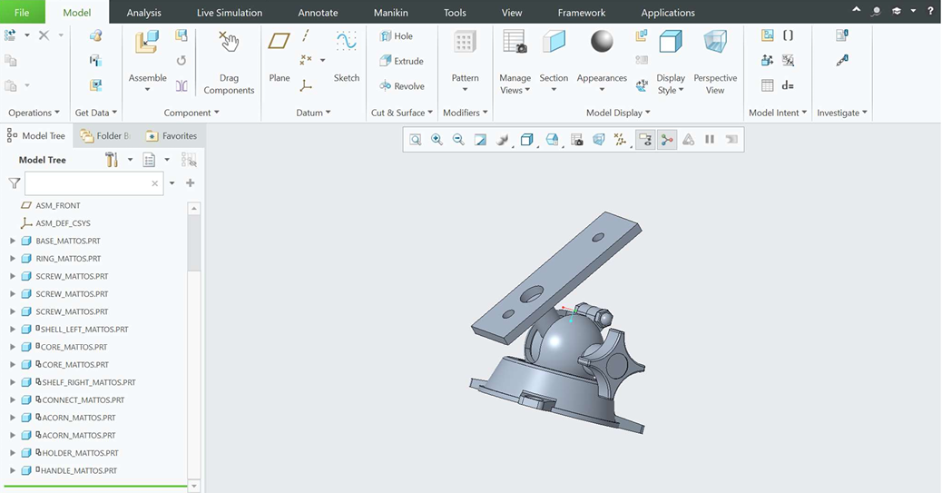
Parametric Part Modeling: Engineered individual steel components from scratch in Creo Parametric using provided geometric constraints, utilizing advanced extrusion, revolve, and pattern operations to model the base, split shells, core, and handle.
- 02
Mass Properties Validation: Computed and validated physical material properties for each component, ensuring accurate volume, surface area, and density (7.827 x 10^-6 kg/mm3 for steel) calculations to confirm design fidelity.
- 03
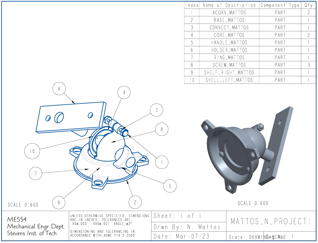
System Assembly: Integrated 10 unique component types into a fully constrained, interference-free master mechanical assembly designed to accommodate the 360-degree rotation and 90-degree tilt of the physical device.
- 04
Engineering Documentation: Produced industry-standard 2D engineering drawings featuring orthogonal 3-view layouts, exploded assembly configurations, and a comprehensive Bill of Materials (BOM) strictly adhering to ASME Y14.5-2009 dimensioning and tolerancing standards.