Index / Work / N° 22
Project N°22 of 24
CategoryFEA · Simulation
Year2025

FEA Stress Analysis of a C-Clamp

Evaluated the structural performance of a C-clamp under simulated operational loads using SolidWorks FEA, validating the normal stress distribution on the inner and outer surfaces against classical theoretical calculations.

Key Engineering Contributions
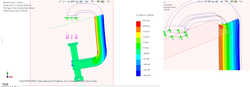
  1. 01
    FEA Modeling: Modeled the structural frame of a C-clamp in SolidWorks, applying opposing boundary loads to simulate the gripping forces experienced during standard workshop operation.
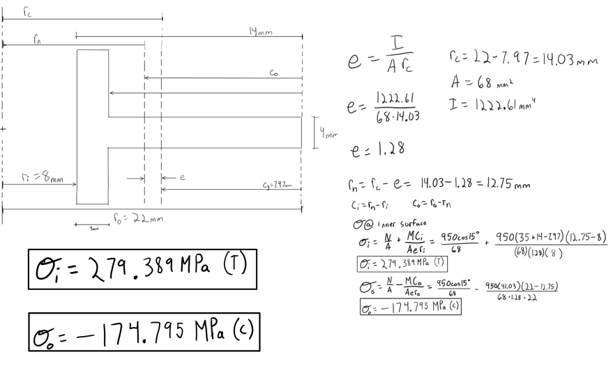
  2. 02
    Stress Analysis: Analyzed the combined axial and bending stresses along the curved section of the clamp, identifying a peak inner surface tensile stress of 279.3 MPa and an outer surface compressive stress of -176.5 MPa.
  3. 03
    Theoretical Validation: Calculated the expected theoretical stresses using classical mechanics equations and compared them directly against the SolidWorks FEA data. Achieved an exceptionally low margin of error (under 1% deviation) for both surfaces, conclusively validating the accuracy and reliability of the computational model.

Visual Documentation

SolidWorks simulation contour plot of the normal stress distribution (σy) on the
Figure 1
01.png
SolidWorks simulation contour plot of the normal stress distribution (σy) on the front face of the frame of the C-clamp model.
Using classical equation to solve for combined axial and bending stresses at the
Figure 2
02.png
Using classical equation to solve for combined axial and bending stresses at the inner and outer surfaces of the c-clamp frame. The inner and outer surface stresses resulted in a 0.0258% error and 0.9
Using classical equation to solve for combined axial and bending stresses at the inner and outer surfaces of the c-clamp frame. The inner and outer surface stresses resulted in a 0.0258% error and 0.975%, respectively.